Showing posts with label staging. Show all posts

Monday, May 20, 2019

NOSE-TO-TAIL STORAGE/STAGING - PART TWO

We are running DCC trains on our layout and we have them in a storage system that runs them nose-to-tail. Can we do this with TWO or more NCE MINI PANEL micro-controllers?


Thomas along with Annie and Clarabel have run into our storage system.  They ran up to our blue sensor and were held there for a while by the red MINI PANEL conroller.  Now it is time for them to run out onto the mainline, and run at faster speeds controlled by a second MINI PANEL that we will call green.  In this image Thomas is crossing over from one section to the other.  If this were a DC world, we could accept this practice. For a brief moment there is a blip while the locomotive straddles both sections and some of the higher voltage green section bleeds back into our lower powered storage section.  It does not create too much fuss.


BUT, in a DCC world, while Thomas is straddling the two sections, and allowing the digital commands to mix, another locomotive being held in storage may have seen a command issued by the green controller for it to run faster. Once Thomas leaves the section, that locomotive may continue to hold-on to that erroneous command, and 'run-away' at faster speed into the back of another stored train.  Obviously we cannot allow this to happen!


So we need to factor in a 'handover' period where the red controller takes charge of part, or ALL of the mainline for a long enough period so all locomotives in the train reach the mainline section, before the green controller takes over.

It is possible to have a short section of mainline track wired to accommodate this HANDSHAKE period, long enough to accept the length of your 'head-end' power [one, two, three or four engines].  Including this section of handover-track, avoids having to give control of ALL the mainline to the red controller.

However, some layouts will feature trains with helper or bank engines spread throughout the train, or bankers on the rear; in which case the delay will need to be much longer, until ALL of the train has passed the sensor; and then allowing a further few more seconds grace period after that.  If you have a handover section, that may need to be long enough to accept your longest train. 

Consider that some passenger trains may also have power units front, middle and/or rear, AND the wheels/tyres of some coaches with lighting will also manage to straddle the gap between sections, creating the same cross-contamination.  My XPT will keep oscillating. It will have power at the front-of-the-train one trip, and rear-of-the-train on the next outing.


Success!  Thomas has made it safely into the new section. The HANDSHAKE is over, the green controller is fully in charge now, and Thomas may now run at mainline speed, and he won't be meddling with the decoders of any other engine held in the storage sidings.


[CLICK ON EACH IMAGE TO SEE IT FULL SCREEN]
[HIT ESCAPE TO RETURN TO THE BLOG]


Sunday, May 19, 2019

NOSE-TO-TAIL STORAGE/STAGING - PART ONE

To control my trains in the spiral staging I need a means of keeping them apart. If I were running a purely DC layout, I might arrange electrical blocks, with gaps cut in the track. My trains would be running at low speed, but even so, when they reached an infra-red sensor (or any type of sensor for that matter - reed switch, photoresistor, LDR, light dependent resistor), when they reached that sensor and the relay opened they would come to a shuddering halt. When power is restored, the train will lurch off, and go on its merry way.

I am not being overly critical - that is how it is. It works!  Since it is in a fiddleyard, the public will not see this unprototypical behaviour.  The system will also run DCC, but again when the relay is triggered the train will come to an abrupt stop - more gentle if a stay-alive is fitted - and care must be exercised, that such locos do not over-run into the next section.  Set the speed of locos in staging slow enough, so this does not occur. Leave sufficient gap between the sensor and the next section.  Also, the sound (if fitted) will stop - the DCC train will be effectively dead. If the same DCC feed is then restored to the tracks, the train will take off, as it would following a power drop-out due to a short-circuit.

Here is an infra-red sensor from Heathcote Electronics in the UK...

http://www.heathcote-electronics.co.uk/

Heathcote Electronics products are imported and promoted in Australia by Warren Herbert and his company Gwydir Valley Models, from Glen Innes, NSW.

http://www.gwydirvalleymodels.com/

Most devices come under the title IRDOT - Infra-Red-Detection-Of-Trains.

Here is one such product - an IRDOT 2 - and on the right hand side, two black boxes marked OKO.  These are the relays.  Each one is a single-pole-double-throw relay, but together they represent a DPDT switch (which comes standard with most DC controllers to allow locomotives to be reversed).


[CLICK ON THE IMAGES TO SEE THEM FULL SCREEN]
[HIT ESCAPE TO RETURN TO THE BLOG]


With an IRDOT 2 (with relays) in conjunction with an IRDOT 1 (which has no relays) placed a distance apart on a section of track, it is possible to run a locomotive or train backwards and forwards between the two sensors in a shuttle operation.  At each end, the train can be held stationary for a controllable period of time, then the DPDT switching by the relays will reverse the current, and the train will head off in the opposite direction and continue indefinitely doing the same thing at either end of the track.  Here is a simple demonstration of that operation on a section of test track and a DC locomotive.

[CLICK THE BOX IN THE LOWER RIGHT CORNER TO WATCH VIDEOS FULL SCREEN]
       [CLICK AGAIN IN THAT BOX TO RETURN TO THE BLOG]


Using the same section of test track, and just two sensors (we do not need the relays on this occasion) wired to an NCE MINI PANEL we can control a DCC locomotive to run with far greater subtlety. We can do slow starts, we can brake gently to a stop - no jerks - and we can include whistles, lights and bells (if available and required).


In this image we can see the two wires running back to the MINI PANEL from the sensors, then a spiral cable connecting the MINI PANEL to a SB5 smart booster, that is actually controlling the train, with the commands coming from the MINI PANEL.


This is the beast doing all the heavy-lifting - an NCE MINI PANEL.  In a future post I will describe how to program this device.

Returning to our DC fiddleyard - let's try to store a train.  Thomas approaches with Annie and Clarabel, and runs all the way through the yard to the blue sensor. We want him to wait here, so when the relays open he stops, with a bit of a shudder.  If we want him to go onto the mainline and do some work, we press the blue button, which supplies some power, and Thomas lurches off with his coaches onto the layout.


When more trains enter storage, they close-up nose-to-tail behind trains that have previously entered staging. BLUE Thomas is already being held. If he were to leave, both relays would close, and power from the second relay would energize PINK Thomas to move up. That is NOT going to happen just now, we want to see what happens to GREEN Thomas. He is receiving power because the green relays are closed. Not only does he have power in the section he is in, but also in the section ahead of him.  He will run all the way up to the green sensor, open those relays and stop.  If BLUE Thomas is released, the other two will advance, in that ABRUPT manner I have been speaking about, until they are also waiting, ready for their turn on the layout.


It is possible to program the same thing into a MINI PANEL and run a nose-to-tail storage yard with DCC. [Again, I will describe the programming of MINI PANELs in a separate post.] In the following video we see three locos being controlled, and there are three IRDOT sensors set up as well. One locomotive enters the mainline and runs through our beautifully landscaped layout and returns to the fiddleyard behind the scenes - the yard is full - so it is held short of the entry point.  The next loco then moves up, and the third, making way for the waiting engine to go into storage.  Once this happens, the lead engine can take to the layout and do its tour of duty.


We can observe one of the downsides to this system - the MINI PANEL is quite linear - it does not do well at multi-tasking - it can only take on one job at a time.  It can only run one engine at a time. In fairness, it does a great job at this, gently accelerating and braking our locomotives.  We could have this system running out on the mainline in public view, stopping trains very gently at signals and starting them again, (also very gently) when the line is clear.  I am sure the public and occasional visitor would be impressed. [In a future post, I will discuss how this is achieved.]

BUT... if we want to have one MINI PANEL controlling the yard, and one MINI PANEL controlling the mainline, the two controllers are going to have to HANDSHAKE.  There is a problem running a loco between two controllers.  When it crosses over from one to the other, the engine's wheels allow signals to cross-contaminate section A and section B.  So during the electronic handshake, we build in a delay, allowing the train leaving section A to completely leave that section before the possibly FASTER power for section B is applied. The handshake will also have to be applied when the loco leaves the mainline section and returns to the yard.

This operation too will be the subject of a future post.

MORE ON THE SPIRAL DESIGN

This is how my spiral is designed.  It is flat in the middle which makes it easy for a person to reach in and adjust any equipment that needs attention.  Trains must drop down into the spiral and climb out of it.  The steepest grade is in the middle where there is also the smallest radius. Trains climb out of the spiral on the outside which has a gentler gradient and also the curves here are of larger radius.

The smallest radius curve is the initial one which takes the train through just one 90-degree quarter-turn at my minimum radius of 20 inches or 508mm. Curves then step out at 2-inch [50.8mm] increments so the remaining radii are 22, 24, 26, 28 with one final quarter turn of 30-inches.

[CLICK ON THE IMAGES TO SEE THEM FULL SCREEN]
[HIT ESCAPE TO RETURN TO THE BLOG]


The grade down into the spiral is 1-in-40 or 2.5%.  Trains can manage steeper grades, with smaller radius curves, so long as they are going DOWN.


The climb out is a gentler grade at 1-in-48 or 2.1% and of further benefit - the radius here is larger - a mix of 28 and 30-inch radius curves.


I have highlighted the 24-inch [609.6mm] radius curve here, to make it easier for viewers to understand how the spiral is constructed.  The curve is interrupted before its final quarter-turn by a two-inch straight.  This straight pushes the spiral to the right, sufficiently for the next larger radius to begin, and creates the 2-inch separation between the tracks.


E
nthusiasts wishing to adopt this plan for storage will need to consider how they will keep the trains separated in this staging yard. One way is to divide the spiral into sections or blocks controlled by relays. [More on that shortly.]  Another way is to allow a set time interval to pass in order to keep the trains apart.  If this approach is chosen, then it is imperative that your locomotives are speed-matched to run at the same speed at a giving setting - say SPEED-STEP 7-of-28, or SPEED-STEP 30-of-128.

CURRENT NEWCASTLE PLAN

Here is my current design for a Newcastle layout drawn using AnyRail.  It is based on the 1937 track plan you can see below. The station throat has been straightened using double-slip points and simplified, to allow easier running for through-traffic on my mythical North Coast Line, which runs under the Hunter River utilising the Brunel inspired Newcastle Harbour Tunnel [?].  The simplified trackplan will also be controlled from computer or tablet, with just a simple single button press, setting multiple points and signals. Access to the shunting neck [which is longer than the prototype] is also via a double-slip point [now], allowing the pilot engine to access ALL platforms, rather than see-saw to reach platform 1 as it had to do in reality.  There is not much room for a yard, which in reality was huge, however there is space for a small goods shed, a loading bank with crane, a carriage shed, and a few coal roads. The arrival and departure roads had to come to the front due to lack of space to the rear.  Of course there is an oil depot, allowing me to rekindle that moment at the terminus of Wickham Branch, where as a small boy I was lifted up onto the footplate of a 19-class, and my love-affair with trains began.

[CLICK ON THE IMAGES TO SEE THEM FULL SCREEN]
[HIT ESCAPE TO RETURN TO THE BLOG]


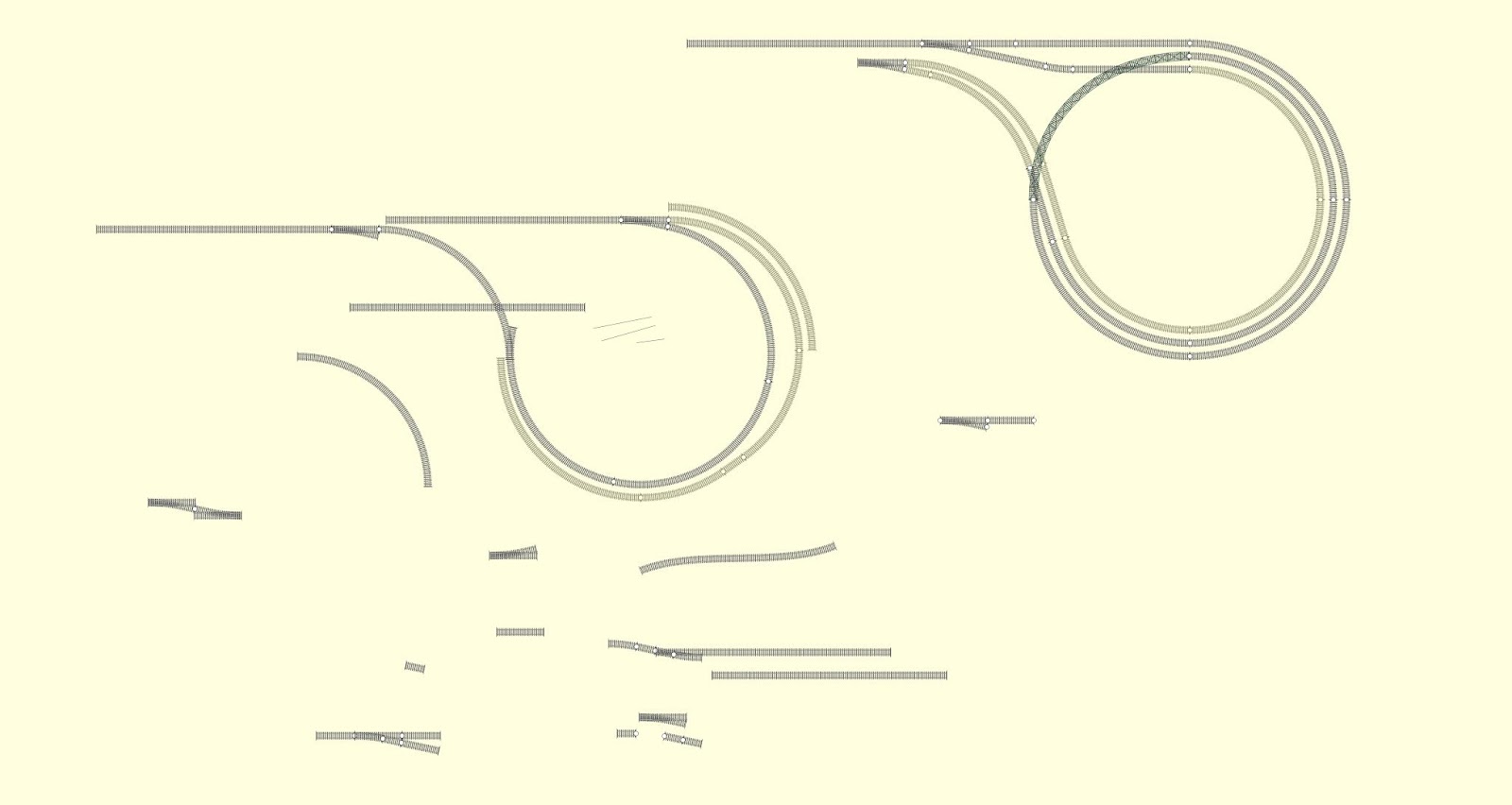
Staging is in the form of a true flat spiral. The idea came to me while playing around with track pieces in AnyRail while designing a return loop, and not wanting to use multiple layover tracks with points, as the points took up so much room.  My design creates 24 metres of storage. 


Only after completing the design, did I remember that maybe I had seen something similar on youTUBE before, and in fact, I had; a creation of James Risner - you can watch his version at the following link.  He runs super-long trains through his trackwork.  I will be running much shorter trains, usually only with one engine, and with timed separation between each train.

https://www.youtube.com/watch?v=qtc__nxtQSc

https://www.youtube.com/watch?v=kN6BXDROBVk&t=95s


For those of you who cannot find the video on youTUBE here is a short sample.


Saturday, May 18, 2019

THE SHORT NORTH LAYOUT - THAT NEVER WAS

This layout was destined to be built in my double garage which at the time had no cars in it - but inhabited by a lot of... 'collectables'... and WE were the only ones who could explain why we wanted to keep them!  The fact that we found it so hard to part with things, was one of the reasons the layout was never built. It did, however, take two or more years of my life to design, using WinRail 10.0, and it featured two levels with a climb up Cowan Bank getting trains to the upper level.  I will never build it - but I think it has a lot going for it, so feel free to pinch my ideas and run with it.  Let me know how you get on.

[CLICK ON THE IMAGES TO SEE THEM FULL SCREEN]

[HIT ESCAPE TO RETURN TO THE BLOG]


Over the years this mythical layout had a number of other names including 'Broadmeadow & Beyond' and 'Mullet Creek'. The layout provided options for many types of rail activity - such as load balancing in Hawkesbury River Yard - adjusting the length and tonnage weight of each train - according to historical records, adding bank engines front and rear and facing the challenge of the steep Cowan Bank, plus a goods-shed and wharf sidings and refuges.  Wyong was expanded to include some of the functionality of Gosford - loco services including a pit with ashing facilities, stockyards, run-in and reverse-in refuges, Steggles, race-day trains, timber siding shunted the wrong way - what WAS I thinking! Ourimbah and Woy Woy had many shunting options. The upper level featured Berowra and a fictitious branch to Lake Cargelligo that included sites that I loved like Ben Lomond, Lue and Carcoar.

ARDUINO - PART THREE: FIRST STEPS

[THIS SERIES COMING SOON]